Safety wire
Safety wire is a backup, not a substitute for torque. Tighten the hardware to the value in the aircraft manufacturer's maintenance data first, then install the wire.
This page is a shop reference, not approved data. It does not replace the aircraft manufacturer's maintenance data or FAA AC 43.13-1B, Chapter 7, Section 7 (paragraphs 7-122 through 7-126). Where this page notes a common manufacturer or SRM practice, or where two FAA sources differ, follow the data that applies to the aircraft you are working on.
What it is for
AC 43.13-1B, paragraph 7-122, defines safetying as securing a nut, bolt, turnbuckle, or similar part so that vibration will not loosen it during operation. These practices are not a way to obtain or hold torque; they only keep the part from disengaging. The usual methods are safety wire, cotter pins, and self-locking nuts. Use new wire on every installation. Do not reuse a run (paragraphs 7-38 and 8-8).
Wire materials
Most work uses corrosion-resistant steel (CRES) lock wire. NASM20995 (also seen as MS20995) codes the alloy with a letter, then the diameter in thousandths of an inch—NASM20995C32 is 0.032-inch CRES.
| Code | Material | Typical use |
|---|---|---|
| C | CRES (commonly 302/304 stainless) | General airframe and engine fasteners |
| NC | Monel (nickel-copper) | Higher heat and corrosive or marine environments |
| N | Inconel (nickel-chromium) | Hot-section and other high-temperature locations |
| CY | Cadmium-plated copper | Breakaway and some seal applications |
Bare copper is sometimes coded CU. Use the alloy the data calls out. Monel and Inconel are the usual high-temperature choices. Where lock wire will touch magnesium, 5056 aluminum alloy wire is commonly specified to limit galvanic corrosion—a practice not stated in AC 43.13-1B, Section 7. Install the material the manufacturer names.
Do not safety emergency mechanisms with stainless steel, Monel, carbon steel, or aluminum alloy wire. That includes switch handles, guards over exit handles, fire extinguishers, emergency landing-gear releases, and similar equipment (7-123). Where the device must work by shearing or breaking the wire, the circular calls for copper or brass safety wire of 0.020-inch diameter only, and the wire must not prevent emergency operation. For seals on first-aid kits, portable fire extinguishers, emergency valves, or oxygen regulators, 7-123b calls for 0.020-inch copper, 0.031-inch aluminum, or another wire named in the applicable technical order. Do not confuse steel with aluminum wire.
Double-twist or single-wire
There are two methods (7-123a and Figures 7-3 and 7-3A). Double-twist is used on most jobs: two strands are twisted together between the parts. Single-wire is for screws, bolts, or nuts in a closely spaced or closed pattern such as a triangle, square, rectangle, or circle, and may also be used on electrical-system parts and in hard-to-reach places.
For the double-twist method (7-123b):
- Use 0.032-inch minimum diameter wire on parts with a hole larger than 0.045 inch.
- 0.020-inch wire, used as a double strand, may be used on parts with a nominal hole diameter between 0.045 and 0.062 inch when the spacing between parts is less than 2 inches.
For the single-wire method, use the largest wire the hole will accept.
Installing the wire
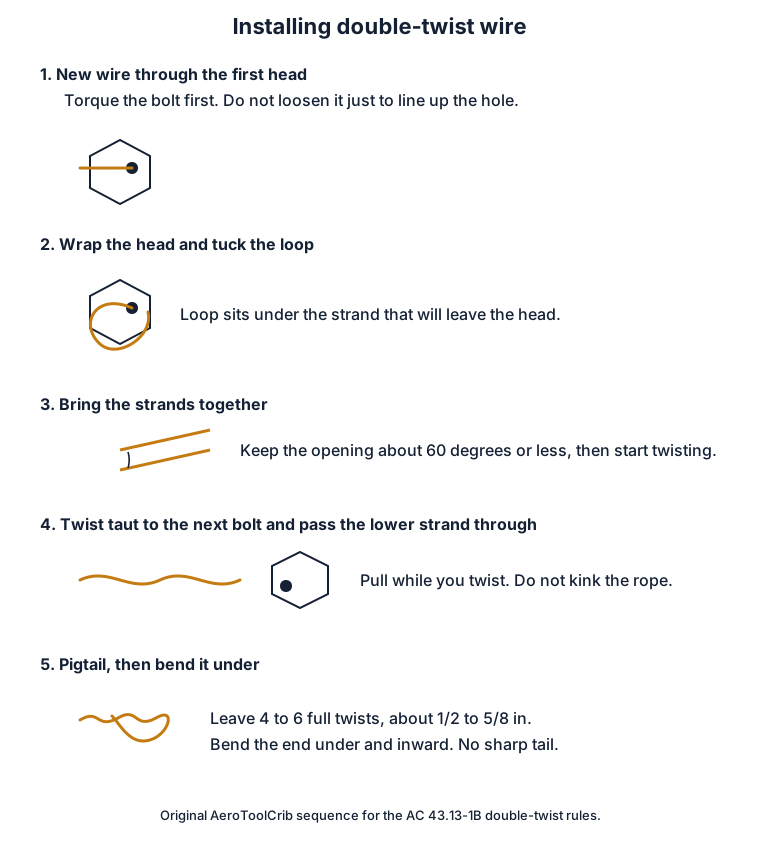
Torque the assembly first. Confirm every lock-wire hole is drilled and that adjacent holes line up. Never loosen a fastener or exceed the specified torque just to catch a hole. If the holes will not line up inside the torque range, use a washer or try another bolt (7-124). For a castellated nut, tighten to the low side of the selected torque range unless the data says otherwise, then continue tightening until a slot lines up with the hole; do not back it off (7-126). Figure 7-3 shows the route for right-hand threads; reverse it for left-hand threads.
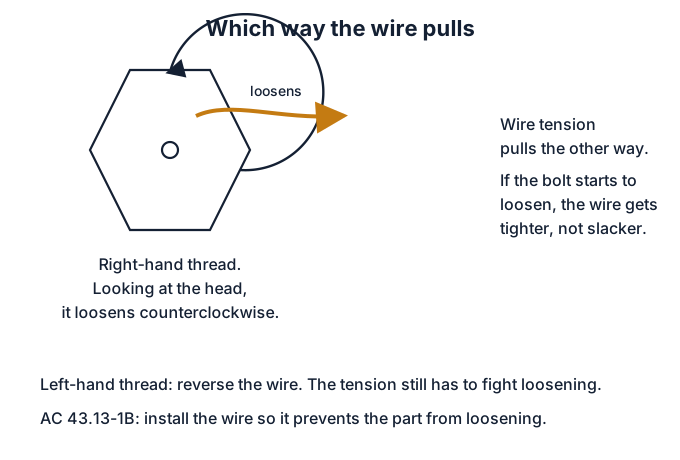
On every run (7-124 and Figures 7-5 through 7-5B):
- Keep the finished wire tight so it does not fret or fail in vibration.
- If a part starts to loosen, the wire must pull in the tightening direction.
- Keep the loop down around the head, close to the contour, and under the outgoing twisted run so it cannot climb and go slack. The strand through the hole should be the one that tightens the fastener.
- Pull taut while twisting; leave a light tension when secured. Do not overstress the wire, or it will break under vibration.
- No nicks, kinks, or damage. Grip the strands at the ends. Never twist the ends off with pliers. Cut old wire close to the hole to remove it.
- If a fitting has a wire lug, start there and keep the wire in line so the lug is not pulled sideways. If there is no lug, wrap tightly around the fitting. Anchor oil caps, drain cocks, and similar single parts to a solid point such as an adjacent fillister-head screw (7-126).
- Bend the ends under and inward so nothing sharp stands out, especially in fuel tanks. Some manufacturer data also requires tank-area ends to be laid back along the wire. Collect the clippings; loose wire is FOD.
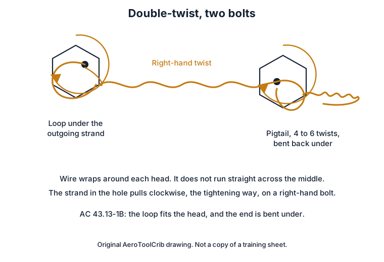
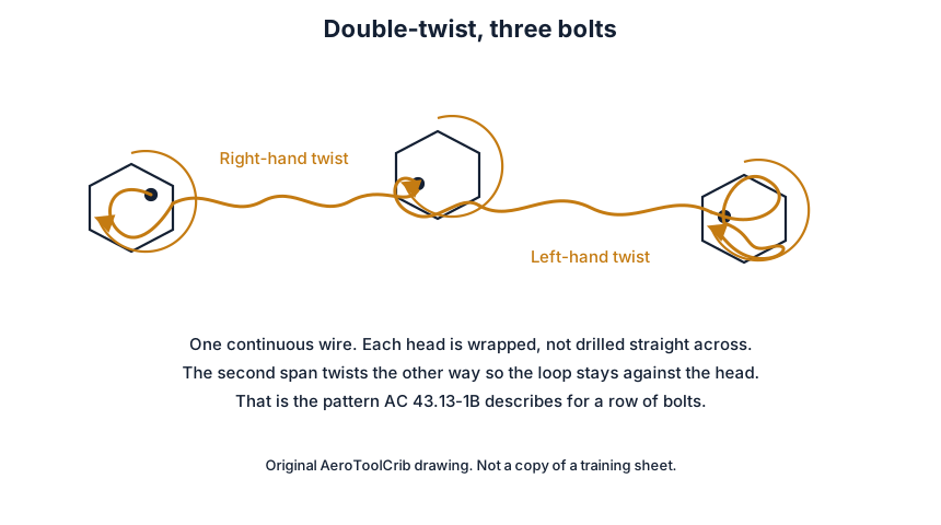
The circular does not cap how many parts may be wired together; 7-124a says the number "depends on the application." FAA-H-8083-30B limits widely spaced double-twist runs to three fasteners, and allows as many closely spaced parts as a 24-inch length of wire will reach. Some AMMs and SRMs also cap the span at about 100 mm (3.94 inches), total length at about 600 mm (23.62 inches), and the series at three items, and may require an extra anchor if the span is longer. Follow the aircraft's maintenance data.
At the end of the run, 7-124 says to leave at least four to six complete turns, 1/2 to 5/8 inch long, after the loop, then bend that pigtail under and inward. FAA-H-8083-30B describes a shorter pigtail of 1/4 to 1/2 inch (three to six twists). Some manufacturer data specifies 10 to 15 mm. If the data sets a length, use it.
Twisting the wire
A wire twister grips the two free ends and twists them when you pull the knob (7-125 and Figure 7-4):
- Grip the wire in the jaws and slide the outer sleeve down with your thumb to lock the handles, or lock the spring-loaded pin.
- Pull the knob. The spiral rod spins and twists the wire.
- Squeeze the handles together to release the wire.
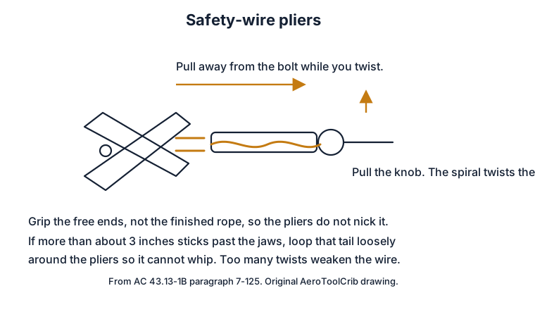
If the wire extends 3 inches or more beyond the jaws, wrap the extra loosely around the pliers so it cannot whip and injure you. Excessive twisting weakens the wire. Some manufacturer standard practices also limit the helix, or twist angle, of the pair, often to about 60 degrees; the circular does not. Twist only as needed for a tight, even run, in the direction that keeps the loop down and the pull in the tightening direction.
Figure 7-3A of AC 43.13-1B shows a typical hand-twisted run at 6 to 8 twists per inch. Many manufacturer standard practices use a diameter-based rate instead, and those tables are not in the AC. Common published rates are about 9 to 12 twists per inch on 0.020-inch wire and 7 to 10 on 0.032-inch wire, with more twists on very small diameters and fewer on heavier wire. Use the rate in the data you are working to.
Turnbuckles
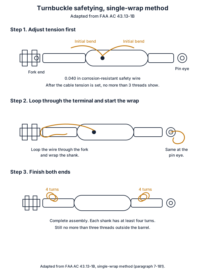
Single-wrap turnbuckle safetying is in AC 43.13-1B paragraphs 7-179 through 7-181 and Figure 7-26D. Leave no more than three threads exposed at either end of the barrel, and wrap at least four turns of wire around the shank on each end. The drawing below follows that figure.
Cotter pins
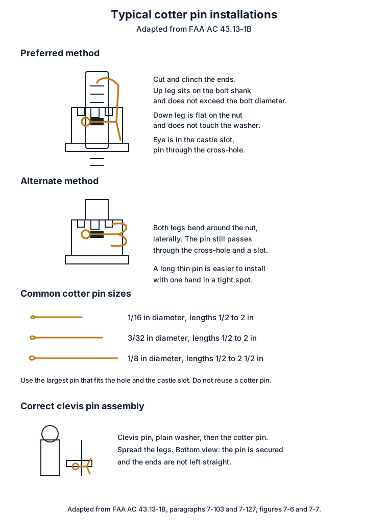
Castellated nuts use a cotter pin through the bolt hole and a slot, not a wire draped over the threads. AC 43.13-1B paragraph 7-127 and Figures 7-6 and 7-7 show the preferred bend (one prong over the bolt end, one down flat against the nut) and the alternate (both prongs wrapped around the nut). The preferred prong over the shank should not stick out past the bolt diameter, and the prong against the nut should not touch the washer.
Sources
- FAA, Advisory Circular 43.13-1B with Change 1, Chapter 7, Section 7, paragraphs 7-122 through 7-126 and Figures 7-3, 7-3A, 7-4, 7-4A, and 7-5 through 7-5B. Also paragraphs 7-38 and 8-8 on reuse. Turnbuckle single-wrap: paragraphs 7-179 through 7-181 and Figure 7-26D. Cotter pins: paragraph 7-127 and Figures 7-6 and 7-7.
- FAA-H-8083-30B, Aviation Maintenance Technician Handbook—General, cited only for series and pigtail figures that are not in the circular.
Always follow the aircraft manufacturer's maintenance data and AC 43.13-1B.